A GIF of the interactive demo seen later in this post.
Questions about the algorithms related to isometric grids are not uncommon. In fact, they are a little more common than you could expect them to be, given the relative simplicity of things.
So I have decided to write a little blog post on the two things important here:
- Converting local isometric grid' coordinates to global screen-space coordinates
- Converting global/screen-space coordinates to isometric grid' local coordinates
Local to global
So, getting global\screen coordinates from local coordinates in a isometric grid.
People tend to overthink this way too much. Essentially, if you look at the isometric axes,
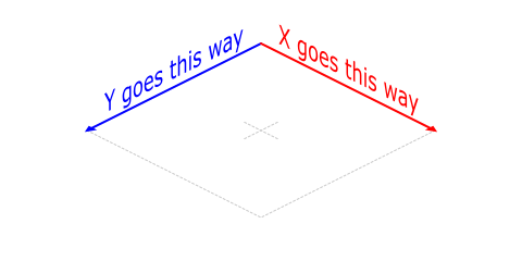
Essentially, as local X increases, global X and Y increase; as local Y increases, global Y increases, but global X decreases. And there's that slant. So that translates to a pair of very simple formulas:
GlobalX = IsoX + (LocalX - LocalY) * IsoW;
GlobalY = IsoY + (LocalX + LocalY) * IsoH;
where IsoX and IsoY are the global\screen coordinates of the grid's starting point (0, 0), while IsoW and IsoH determine the grid's scale and slant (2, 1 for standard 2:1 proportions).
Global to local
Getting "in-grid" local coordinates from global/screen coordinates is a bit trickier (as it requires you to reverse the two formulas seen before), but manageable. Moreso that it's done already:
LocalX = ((GlobalY - IsoY) / IsoH + (GlobalX - IsoX) / IsoW) / 2;
LocalY = ((GlobalY - IsoY) / IsoH - (GlobalX - IsoX) / IsoW) / 2;
A little demo
Combining the above is enough to assemble a little demo that would both handle an isometric grid (by converting relative coordinates to screen coordinates for drawing cells) and mouse input (by converting screen coordinates to grid coordinates and then back):
Mouseover to interact.
Depth-sorting
Another topic worth touching here is depth sorting (or drawing order).
An obvious approach would be to sort objects based on their vertical position.
With isometric grid, however, that would also mean developing a rather strange routine to draw the grid (going in "diagonal lines"), which may not be something that you want to do.
But, with axes lined up as shown, simply drawing things with a pair of for-loops (one for each axis, whatever order) like so
for (x = 0; x < 8; x += 1) {
    for (y = 0; y < 8; y += 1) {
        DrawIsoTile(x, y)
    }
}
will give you the correct and desired effect:
Mouseover to interact
Ground tiles (if any) are drawn first, then the object(s) are drawn on top of them. If multiple objects can occupy the same tile at different sub-positions, they are to be sorted based on vertical position.
If there are any other things that I didn't cover here, do tell.
Downloads
- GameMaker: .GMZ · web demo · port of the "little demo" to GML
Edit: Also check out the standard isometric demo (how to find) - JavaScript: gist · web demo
Have fun!
Great tutorial, really helped me visualize and fully understand!
Everything works… sort of.. for me.. the conversion for screen coordinates to cells is off by 1… on the y axis only… no idea why.
Ever had this issue?
Hello YAL!
If I was trying to highlight a specific grid cell that the mouse is over, how would I convert the to_grid script to lock to the area of a cell to show what area the the mouse is over?
I have done this with more traditional grids but im a bit confused when looking at a the grid when its being converted.
Thank you!
You would want the formula from “global to local” for that
thank you so much, my apologies for missing over that.
How would I go about doing the strange diagonal line check? I am not working on an asymmetrical grid that I can rotate, and the math is alluding me. I am doing the method you have mentioned above, but im still getting draw order problems because I am stacking items and the object is bigger than 1 square, so I believe the diagonal method is the way to go.
Currently I have a rather complicated check on whether there are more columns or rows, and whether you have passed the end of the row or not, but im not sure thats the right direction.
Thank you again
So i’ve been meaning to try and “stack” isometric blocks, something like the following image, https://imgur.com/a/h3dCWnC, however i’ve been having problem regarding depth-sorting, when there are piles of blocks behind another pile or in front of another pile it messes up the drawing order, is there any solution that may help me tackle this problem? Another thing I might add is that I substituted the “draw sprites” for objects, since it makes more sense to me.
Thanks in Advance.
If multiple entities have the same position, you would want them drawn from bottom to top, thus counting in Z divided by a large value for depth sorting.
It worked thanks! However I had to change thing a little bit as I wanted it to generate the blocks dinamically, but using global variables kinda worked out, so again thanks for your help!
Hello, first of all, thank you for publishing this. Second, dropbox links are dead, can you please fix them?
Fixed – the only remaining dropbox links were for that standard example image and for JS demo (which I’ve put up code for on gist anyway)
Hello
This is very nice tutorial as always on your website, but I see some problem with demo project web and gmz.
Very important in iso games is place/movement direction angles. It should be 0,45,90,135 etc. In your sample I see here direction is round, this is no problem, but objects (cars) moving not on straight angles and this is visible (shaking a little etc). Whole idea of good isometric projection is to have nice pixel lines. Here is good example http://flarerpg.org/tutorials/isometric_intro/ In short words, car should move in mentioned directions only too (0,45, 90 ….).
I’m asking, because I like your articles, and I’m looking for good and simple solution for game maker isometric grids. I have some pro component, but here also same issue. Can you look on this?
Thank you, Pawel
Firstly, this is a great post as usual. My question would be how to convert screen angles to world angles?
For example, an object in the center of the grid pointing to the center of the top-right edge of the grid would return 0, pointing to the top corner would be 45, the center of the top-left edge would be 90, etc.
Is there a simple way to ‘skew’ the angles of the screen to make sense from the world’s point of view?
Thank you.
You can convert iso coodinates to normal and calculate angle.
In right manner you need manipulate all data in normal coordinates and after that only _show_ state in iso coordinates. Just imagine you have top-down game
and everything will fall into place.
If you know what that is a MVC, that Model have normal coordinate, but view – have iso coordinate, after changing model, you only need to show changes in right manner.
Indeed, while you can’t “skew” an angle itself, you can always convert it to a vector, skew that, and get the new angle. For example, with 2:1 tile proportions and radians, it could be something like
If it’s an angle between points, quite often you can simply convert both points to isometric coordinates, and find an angle between those (now in isometric space).
As WeslomPo has mentioned, it’s easier to get a grasp of if you consider that the actual game world remains top-down and conversions only happen when drawing things.
Thanks for the replies!
I’ve been playing around with these isometric concepts, and I think I’m gaining a better understanding of them.
I appreciate the help.